In our first attempt to eliminate the backing glass layer
and use flat mirrors alone, we mounted them directly to a parabolic surface. We
had developed a technique to accurately curve aluminum extrusions by
systematically hitting the outboard leg with a ball peen hammer. Increasing the
number of hits per length or the force used reduces the focal length of the
parabola until it matches a template. The photo below shows a truss with a
curved top member.
Aluminum Truss With Parabolic Top Member and Discretely Bent Bottom
Member
A number of these trusses made up the concentrator structure
by attaching them to two girders that were discretely bent so the parallel
trusses formed a parabola in the transverse direction. This parabolic surface
was then lined with corrugated polycarbonate roofing material, see photo below.
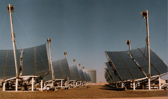
Parabolic Concentrator Structure, with Left
Side Covered with Corrugated Roofing
We directly attached mirror facets
to the corrugated sheet using a variety of methods but none were satisfactory.
Also, solar images reflected by these mirror facets mechanically attached to
the corrugated sheet did not all superimpose at the target focal length hit
each so did not concentrate sunlight enough to warrant continuing this option.
Another drawback to this approach: we found no way to ascertain which mirrors needed
correcting nor was there any way to tweak mirrors that did not direct sunlight
to the target center.
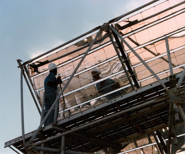
Mirror Facets Attached to the Corrugated Parabolic
Surface
We next tried two methods to form
plastic materials into mirror panels: heat-forming thermoplastic structural
sheets and molding fiberglass and resin, see photo below. Although both these
methods may work in dedicated mass-assembly lines with multiple copies of dedicated
tooling, neither approach proved workable as a boot-strap process because they
required too much labor that would take too long to produce adequate results. Also,
these materials were expensive and would probably not weather well for thirty
years.
Thermo-formed Twin-wall Polycarbonate Panel-Based Mirror Assembly with Reflection on Target
Male Mold for Both Heat-forming and Casting
Mirror Assemblies
A series of mirror assemblies that
used the hammering technique to stretch aluminum material behind the parabolic
surface delivered ever-improving performance. These fastened curved mirror support members
between straight end pieces with features that enabled stacking mirror
assemblies one on top of another.
Mirror Assembly Intensifies Sunlight to
Target the Same Size
Mirror Assembly Using Aluminum Rod Pullback
Supports
Rear View of a Mirror Assembly with Four
Curved Mirror Support Members Between Straight Ends with Stacking Features, One
Foot Square Mirror Facets and Angle Mirror Pullback Supports
Stacked Mirror Assemblies with Candidate
Mirror Pullback Support Options
One Foot Diameter Image of 3 x 3 Array of Warped
One Foot Square Mirrors
Computer Model of a Dish Solar Collector
Showing Where Concentrator Offset Alignment Features Are Required at Each
Corner to Attach Mirror Assemblies to Underlying Trusses: Corners of Four Separate
Mirror Assemblies Meet at a “Quad”
Mirror Assembly Fabrication Fixture That
Insures Mirror Supports Form Parabolic Surface with a Mirror Assembly Clamped
In Place
Stacked Mirror Assemblies With One on Top That
Has Three 1 x 3 Foot Mirrors and Offset Alignment Features That Enable One
Person Align and Fasten Them Close Together from the Front
A 3 x 3 Foot Mirror Assembly with Two 1 x 3
Foot Mirror Facets Mounted Against Their Respective Curved Members Using Three
Pullback Fasteners (Bicycle Spoke Ferule + Machine Screw)
Mockup of a “Quad” Mirror Assembly
Alignment Feature That Allows One Person to Mount and Adjust Each of Four Corners
So That a Reflected Image Hits a Target at the Concentrator Focal Length. The
Curved Mirror Support Member Shows Hammer Marks that Stretched the Leg Behind
the Mirror Supporting Surface. Alternate Columns of Mirror Assemblies Are
Offset So That One Can Be Removed, Replaced and Realigned Without Moving
Another


